Colwick Industrial Estate
Colwick,
Nottingham, NG4 2BB
Projects - Dorney Bridge
The box was constructed in reinforced concrete in a casting pit adjacent to the railway. It was 50m long, 22.65m wide and 9.45m high. It would have to be jacked through the embankment without causing any disruption to the trains running on the railway lines just 5.6m above.
175 x 90mm diameter horizontal freeze tubes were drilled through the embankment with an additional 8 observation holes for temperature monitoring. The lengths were up to 60m, set out in eight rows vertically up the embankment. The hole centres were bored in a 1.2m x 1.5m pattern. Overall the envisaged minimum dimensions of the frozen block of ground for design purposes were 29.9m wide by 13.65m high. This gave a frozen ground thickness of 2.1m above the roof of the box and below the floor, with 3.275m at either side. The crown of the freeze wall was only 3.5m below the railway tracks.
Surveying of the holes was a very important aspect as it was essential to know the correct positions of the freeze tubes relative to each other to ensure that homogeneous freeze growth was established.
BDF installed four Grasso RC9311 refrigeration plants giving a total of 880,000kcal/hr when discharging brine at -25oC. To meet the stringent local authority noise regulations, the inside of the whole refrigeration plant building was lined with noise absorbent material.
The freeze tubes were connected in groups of four without the use of inner pipes as both ends of the freeze tubes were exposed on either side of the embankment. The pipe ends on the south side were linked together with 50mm diameter flexible hoses. The delivery to the first freeze tube in each of the 20 circuits of the perimeter tubes was equipped with an electromagnetic flow meter. The return of the last tube in the circuit was fitted with a thermocouple to enable the whole flow regime to be balanced. The total volume of brine in the system was approximately 83,000 litres.
Temperature measurements were regularly taken during the growth of the frozen ground. The freeze was monitored by 8No. equally spaced observation holes drilled parallel to the freeze tubes, 1.0m outside the perimeter holes. Each observation hole was furnished with a series of thermocouples wired into data loggers, which were linked to the sit office based computer. The freeze plants, perimeter freeze tube return temperatures and flow meters were also linked into data loggers to be constantly monitored and logged.
Phase 1 consisted of 85No. freeze tubes, split into four rows below the water table. Freezing this section of the gravels and the top of the chalk started on Friday 5th March 1999. After 7.5 weeks of freezing, the lower freeze wall was closed, preventing any upward migration of water, which would have increased the heave to the railway tracks. Phase 2 started on the 27th April 1999, 7.5 weeks after Phase 1. This consisted of 90No. freeze tubes, split into four rows above the water table. Excavation started on 19th July 1999 after 19.5 weeks of freezing.
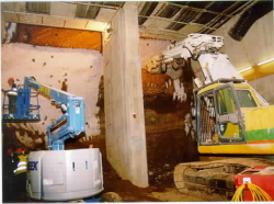
Once the freeze was in place the concrete box culvert was jacked towards the embankment. Frozen ground was excavated from within the box as it moved forwards to allow further progression. An overcut of just 50mm was allowed in order to minimize settlement. The freeze enabled the wall of the excavation to stand unsupported and provided strength to the roof and side walls.
The six week jacking operation started in July 1999 and was completed as planned in August 1999. Freezing finished on the 10th October 1999 after 31 weeks of freezing.
Ground freezing was successfully adopted to provide ground stability and prevent water ingress during the work. Predicted temperature drawdowns, freeze growths, ground heave and thaw settlements were extremely close to the actual values and were sufficient to ensure that the ground freezing design and control measures were properly engineered to the design criteria.

